The principle and working mechanism of wireless PCB antenna
Introduction
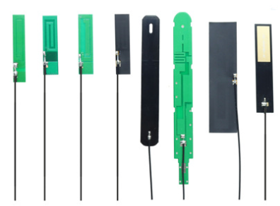
Radio PCB antennas are often overlooked when it comes to designing and manufacturing a radio. However, the antenna is a critical component that allows a radio to pick up signals and broadcast them. This article is going to bring to light the mechanism and functionality of radio PCB antennas, different types of PCB antennas and their advantages and disadvantages, and finally, tips for designing antenna PCBs that can enhance signal strength and reception.
Working Mechanism of Radio PCB Antennas
Radio PCB antennas work by creating an oscillating electromagnetic field around a conductor or a set of conductors. When an electromagnetic field reaches the antenna, it creates an alternating electric current. The oscillation frequency of the electric current is the same frequency as the electromagnetic field that reaches the antenna.
Types of Radio PCB Antennas
There are various types of radio PCB antennas. The most common types are the whip antenna, the patch antenna, and the loop antenna.
Whip Antennas
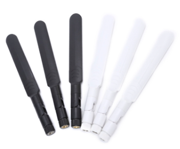
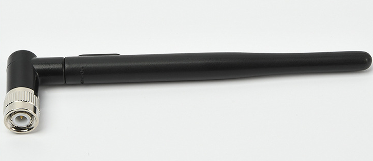
Whip antennas are usually flexible rods or wires that protrude from the radio. They are easy to manufacture and install, making them ideal for mobile and handheld applications. Whip antennas are omnidirectional, meaning they receive signals from all directions. They are also more suited for high-frequency signals than low-frequency signals.
Patch Antennas
Patch antennas are small, flat, and rectangular in shape. They are commonly used in GPS applications and mobile devices, such as smartphones and laptops. Patch antennas are directional; they receive signals from a particular direction. They have better performance in low-frequency applications than whip antennas.
Loop Antennas
Loop antennas are looped metal conductors. They are found in AM radios and antenna arrays. AM radios use the loop antenna to nullify the electromagnetic field to improve selectivity.
Advantages and Disadvantages of Radio PCB Antennas
One of the significant advantages of using PCB antennas is that they are easy to manufacture and install. Additionally, they have a low profile, making them ideal for space-constrained applications. PCB antennas have a high-quality factor, meaning they can efficiently transmit and receive signals.
However, PCB antennas also have some disadvantages. They have a limited range, particularly for lower frequency signals. They can also be affected by the material and the surface they are mounted on, which can reduce their efficiency.
Tips for Designing Antenna PCBs
When designing antenna PCBs, it's crucial to consider the following tips:
Trace Width
A wider trace will have lower resistance and will be able to carry more current, which is essential for high-frequency signals.
Trace Length
When designing a PCB antenna, the trace length should be proportionate to the wavelength of the signal it is designed to receive. A trace that is too long or too short may lead to signal distortion.
Trace Path
The path of the trace is critical, mainly when designing a directional antenna. The path should be as direct as possible and without any sharp corners that may cause signal loss.
Ground Plane
A ground plane is essential to reduce the radio frequency interference (RFI) that can affect the signal quality. The ground plane should be as large as possible, covering the entire area under the antenna.
Conclusion
The radio PCB antenna is a critical component that plays a significant role in signal reception and transmission. Different types of antennas have different advantages and disadvantages, and their design should consider the signal frequency and application requirements. The success of an antenna PCB design depends on the consideration of trace width, trace length, trace path, and ground plane. A well-designed antenna can enhance signal strength and reception and reduce radio frequency interference.
